
Valve guide replacement is crucial for maintaining engine efficiency and performance. Worn guides can lead to oil consumption and reduced power. Learn how to replace them effectively.
1.1 Importance of Valve Guides in Engine Performance
Valve guides play a critical role in engine performance by ensuring proper valve alignment and reducing oil consumption. They prevent valve stems from wobbling, which can lead to inefficient combustion and reduced power. Worn or damaged guides can cause oil to leak into the combustion chamber, increasing emissions and decreasing efficiency. Replacing valve guides is essential to restore engine performance, prevent further damage, and maintain optimal fuel efficiency. Properly functioning guides ensure smooth engine operation and longevity.
1.2 Signs of Worn or Damaged Valve Guides
Worn or damaged valve guides often exhibit symptoms like increased oil consumption, reduced engine performance, and excessive smoke from the exhaust. Noisy valves, poor fuel efficiency, and rough engine operation are also common indicators. If the valve guides are severely damaged, the valve stem may wobble, causing improper sealing and potential engine damage. Addressing these issues promptly is crucial to prevent further deterioration and maintain optimal engine functionality. Regular inspections can help identify worn guides early.
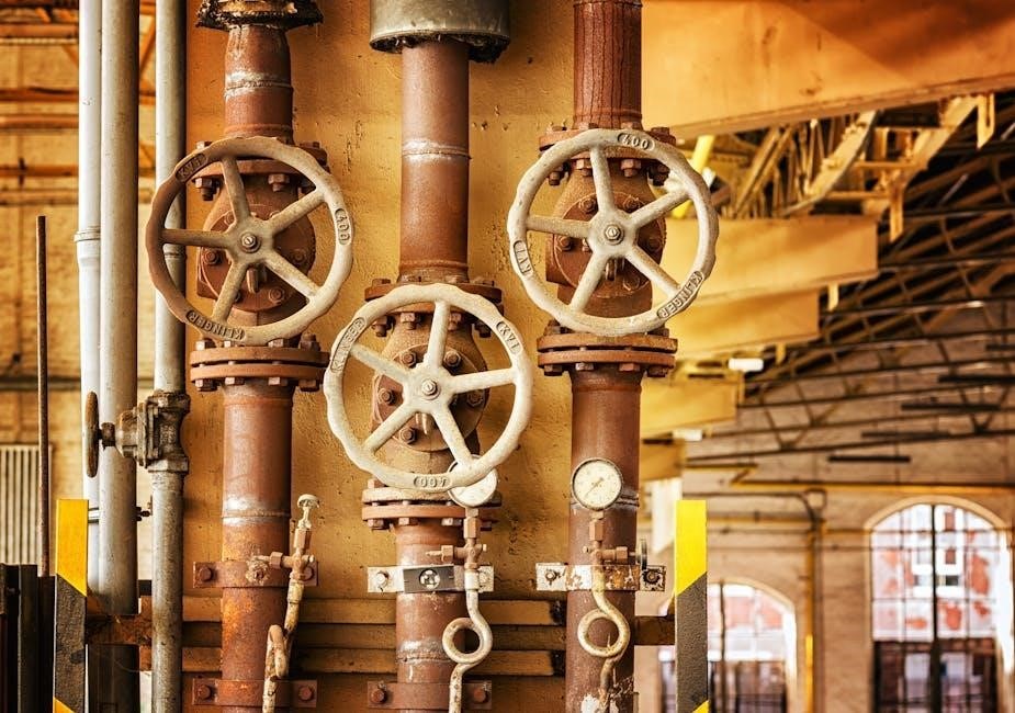
Essential tools include an air hammer, valve grinder, and dial indicator. Materials required are bronze guides, anti-gall lubricant, and liquid CO2 for efficient guide removal and installation. An air hammer is vital for driving out old guides and installing new ones. A valve grinder ensures precise valve face resurfacing, while a dial indicator measures guide alignment. These tools are indispensable for a successful valve guide replacement, ensuring accuracy and efficiency throughout the process. They help maintain engine performance and prevent future issues related to misaligned or worn components. Bronze guides are durable and resistant to wear, making them the preferred choice for replacement. Anti-gall lubricant prevents friction and ensures a smooth fit. Liquid CO2 is used to chill and shrink the guides for easier installation. Together, these materials ensure a precise and long-lasting repair, maintaining engine efficiency and preventing future damage. Proper use of these materials is essential for a successful valve guide replacement. Proper engine preparation ensures a smooth replacement process. Drain coolant, remove the cylinder head, and secure the engine. Position the piston correctly for access to guides. Draining the coolant is essential to prevent damage during cylinder head removal; Once drained, carefully detach the head from the engine block using appropriate tools. This step ensures access to the valve guides for replacement. Secure the head on a workbench to avoid any accidental damage. Proper preparation here is key to a successful valve guide replacement process. Securing the engine prevents movement during the replacement process. Position the piston at Bottom Dead Center (BDC) to ensure proper clearance. Use a piston stop or stuff small rope into the cylinder to hold it in place. Rotate the engine backwards to push the piston down gently. This step ensures the valve train remains stable and avoids potential damage. Proper alignment is critical for a successful valve guide replacement. Old valve guides are removed using an air hammer or liquid CO2. The air hammer drives out the guides, while CO2 freezes them for easy extraction. Secure the engine during this process to maintain stability and avoid damage to surrounding components. Proper removal ensures a clean start for installing new guides. Using an air hammer is a common method for removing old valve guides. The tool delivers precise, controlled blows to drive out the guides without damaging the engine block or cylinder head. Proper alignment and steady force are essential. This approach is efficient and widely recommended, requiring minimal setup and ensuring safe removal. Always use appropriate chisels and maintain consistent pressure for optimal results during the extraction process. Liquid CO2 offers a unique approach to guide extraction by freezing the guides, causing them to contract and loosen. This method minimizes damage to the cylinder head. The frozen guides typically drop out effortlessly, eliminating the need for harsh force. It’s a recommended technique for delicate engines or when traditional tools might cause harm. The process is efficient and preserves engine integrity, making it a preferred alternative for precise guide removal. Install new guides using a press or liquid CO2 method, ensuring proper alignment and fit. Apply anti-gall lubricant to prevent damage and ensure a precise installation. Pressing in new valve guides requires precision to avoid damage. Use a hydraulic press or specialized tool to ensure the guides are seated correctly. Apply anti-gall lubricant to prevent galling during installation. Align the guide with the cylinder head’s bore, ensuring straight insertion. Once pressed in, inspect the guide’s position and height to confirm proper fitment. This step is critical for maintaining engine performance and preventing future issues. Using anti-gall lubricant is essential during valve guide installation to ensure proper fitment. Apply a thin, even layer to the guide’s outer surface to prevent galling and promote smooth seating. This lubricant reduces friction, allowing the guide to press in evenly without damage. Proper application ensures the guide aligns correctly with the cylinder head, maintaining precise clearance and preventing future wear. This step is vital for achieving a secure, long-lasting installation. Machining involves boring and reaming guide holes to precise specifications. Fitting requires milling the guides to ensure proper height alignment, essential for optimal engine performance and durability. Boring and reaming are critical steps in valve guide replacement. Using specialized tools, the old guide holes are enlarged to precise dimensions, ensuring a snug fit for the new guides. This process requires high accuracy to maintain proper alignment and prevent engine damage. After boring, reaming smooths the surface, preparing it for the installation of the new bronze guides, which are essential for optimal engine performance and longevity. Milling ensures the new valve guides are set to the correct height, critical for proper valve train geometry. Using a milling machine, the guides are carefully adjusted to specification, ensuring the valve stem seals properly. This step prevents issues like valve float or improper seating, which can degrade engine performance. Precision is key to maintaining optimal clearance and alignment, essential for the engine’s overall functionality and longevity. Thorough inspection ensures proper fitment and alignment of the new valve guides, verifying they meet specifications for optimal engine performance and durability. Using a dial indicator, measure the alignment of the new valve guides to ensure they are within acceptable tolerances. Proper alignment prevents valve train wear and maintains engine efficiency. Proper valve stem-to-guide clearance is critical for smooth engine operation. Use a dial indicator to measure and verify the clearance matches manufacturer specifications. Excessive clearance can lead to valve train noise and wear, while too little may cause seizing. Ensure the valve stem moves freely within the guide, and apply anti-gall lubricant for optimal fitment. This step ensures reliable performance and prevents future engine issues. After replacing the valve guides, reassemble the engine components. Test engine performance to ensure proper functionality. This step confirms the success of the replacement process. After replacing the valve guides, reattach the cylinder head securely. Tighten all bolts in a star pattern to prevent warping. Reinstall the spark plugs and reconnect any disconnected components. Refill the coolant and oil to recommended levels. Ensure all gaskets are properly sealed to avoid leaks. Double-check the valve train and timing components for alignment. This meticulous process ensures the engine operates smoothly post-replacement. Proper reassembly is critical for optimal performance. After reassembling, start the engine and listen for unusual noises. Check for oil leaks around the valve area. Monitor the temperature gauge to ensure proper coolant circulation. Drive the vehicle to assess performance improvements. Look for reduced oil consumption and increased power. Use a scan tool to check for error codes. A proper test ensures the replacement was successful and the engine operates efficiently. This final step confirms the effectiveness of the valve guide replacement. Valve guide replacement is essential for maintaining engine efficiency and performance. Proper tools and precise fitment ensure success. Always follow best practices for optimal results. Replacing valve guides involves draining coolant, removing the cylinder head, and using tools like an air hammer or liquid CO2 for extraction. New guides are pressed in, ensuring proper alignment with a dial indicator. Machining and milling are often required for precise fitment. Anti-gall lubricant prevents damage during installation. Testing clearance and alignment post-installation ensures optimal performance. Following these steps carefully maintains engine efficiency and extends its lifespan. Proper tools and precision are essential for success. Precision is critical in valve guide replacement to ensure proper engine function. Misaligned or improperly fitted guides can lead to reduced performance, increased oil consumption, and potential engine damage. Using tools like dial indicators guarantees correct alignment and depth. Machining and milling must be done accurately to maintain the engine’s integrity. Attention to detail ensures longevity and optimal operation, emphasizing the need for skilled technicians or specialized tools to achieve precise results and avoid costly repairs.
Tools and Materials Needed for the Job
2.1 Essential Tools: Air Hammer, Valve Grinder, and Dial Indicator
2.2 Required Materials: Bronze Guides, Anti-Gall Lubricant, and Liquid CO2
Preparing the Engine for Valve Guide Replacement
3.1 Draining Coolant and Removing the Cylinder Head
3.2 Securing the Engine and Positioning the Piston
Removing the Old Valve Guides
4.1 Using an Air Hammer for Guide Removal
4.2 Alternative Method: Liquid CO2 for Guide Extraction
Installing the New Valve Guides
5.1 Pressing in the New Guides
5.2 Using Anti-Gall Lubricant for Proper Fitment

Machining and Fitting the Valve Guides
6.1 Boring and Reaming the Guide Holes
6.2 Milling the Guides to Proper Height

Inspecting and Testing the New Guides
7.1 Checking Guide Alignment with a Dial Indicator
7.2 Ensuring Proper Valve Stem to Guide Clearance
Final Assembly and Testing
8.1 Reassembling the Engine Components
8.2 Testing Engine Performance Post-Replacement
9.1 Summary of Key Steps and Best Practices
9.2 Importance of Precision in Valve Guide Replacement