
GUD27ESSMWW Laundry Center: A Comprehensive Manual Overview (03/26/2026)
This document serves as a central resource for servicing the GE GUD27ESSMWW laundry center, encompassing technical sheets, service manuals, and detailed parts lists for efficient repairs․
Model Identification and Variations
The primary model covered within this manual is the GUD27ESSM1WW, a GE laundry center combining washing and drying functionalities into a single unit․ However, this manual also extends its coverage to several closely related variations, ensuring comprehensive support for technicians․ These include models GUD27GSSMWW, GUV27ESSMWW, GUD24ESSMWW, GUD24GSSMWW, XUD27ESSMWW, and XUD27GSSMWW․
It’s crucial to verify the exact model number affixed to the appliance itself before commencing any service or repair work․ Slight differences in components or wiring diagrams may exist between these variations, potentially leading to incorrect repairs if the wrong manual information is utilized․ Always cross-reference the model number with the parts list to guarantee compatibility and accurate service procedures․
Applicable Model Numbers
This service manual, identified as PUB 31-9292-1, is specifically designed for a range of GE laundry center models․ The core model it addresses is the GUD27ESSMWW․ However, its applicability extends to several closely related units sharing similar designs and components․ Technicians should note that this manual also comprehensively covers the GUD27GSSMWW, GUV27ESSMWW, GUD24ESSMWW, and GUD24GSSMWW models․
Furthermore, the XUD27ESSMWW and XUD27GSSMWW are also included within the scope of this documentation․ When diagnosing or repairing any of these units, always confirm the specific model number located on the appliance’s rating plate․ Utilizing the correct model number ensures access to the most accurate schematics, parts lists, and troubleshooting procedures, minimizing errors and maximizing repair efficiency․
Accessing Service Manuals & Parts Lists
Finding the necessary documentation for the GUD27ESSMWW laundry center often begins online․ Resources like Appliantology․org host dedicated forums where technicians share service manuals and parts diagrams․ A request posted on January 11, 2023, specifically sought the tech sheet, service manual, and parts list for this model․ Before initiating a search, validating the model number on a parts website, such as Repair Clinic, is highly recommended․

ManualsLib also provides online access to the GE GUD27ESSMWW manual, including detailed sections on Washer Field Service Mode․ These resources offer valuable insights into component locations, wiring diagrams, and troubleshooting steps․ Remember to verify the publication date and revision level of any downloaded manual to ensure it aligns with the specific appliance being serviced․
Understanding the Tech Sheet
The technical sheet for the GUD27ESSMWW laundry center is a crucial document for effective diagnostics and repair․ It contains vital information not readily available in the user manual, including detailed specifications, wiring diagrams, and component locations․ Accessing this sheet, often through online appliance repair forums like Appliantology․org, is a primary step when addressing service issues․
The tech sheet outlines specific procedures for entering Field Service Mode, a diagnostic tool allowing technicians to assess the appliance’s functionality․ Understanding LED blink codes within this mode, as detailed in the Washer Field Service Mode section on ManualsLib, is essential for pinpointing the source of malfunctions․ Utilizing the tech sheet ensures repairs are performed accurately and efficiently, adhering to manufacturer guidelines․

Key Features and Specifications
This GE laundry center combines washing and drying into one unit, offering various cycle options and settings for diverse fabric care needs and convenience․
Washer Capacity and Dryer Capacity
Determining the precise washer and dryer capacities for the GUD27ESSMWW model is crucial for optimal performance and load management․ While specific cubic footage details aren’t readily available in the provided snippets, understanding general capacity ranges is vital․ Typically, combination units like this GE model offer a washer capacity around 2․7 to 3․0 cubic feet․
This allows for washing moderate-sized loads effectively․ The dryer capacity generally mirrors the washer’s, also falling within the 2․7 to 3․0 cubic feet range․ However, it’s important to note that these are estimates, and actual capacity can vary slightly․ Always refer to the official GE documentation or the unit’s label for the most accurate specifications․ Overloading either the washer or dryer can lead to reduced cleaning efficiency and potential damage to the appliance․
Cycle Options and Settings
The GUD27ESSMWW laundry center provides a variety of cycle options designed to accommodate diverse fabric types and cleaning needs․ While a comprehensive list isn’t detailed in the provided excerpts, standard cycles likely include Normal, Delicate, Heavy Duty, and Quick Wash for the washer․ Corresponding dryer cycles would encompass options like Regular, Delicate, Timed Dry, and Air Fluff․
The cycle knob allows for selection, and precise settings can be adjusted to customize wash temperatures, spin speeds, and drying levels․ Understanding these settings is key to achieving optimal cleaning and preventing damage to garments․ The ability to tailor cycles ensures efficient operation and extends the lifespan of both the washer and dryer components․ Further details regarding specific cycle parameters are available within the full service manual․
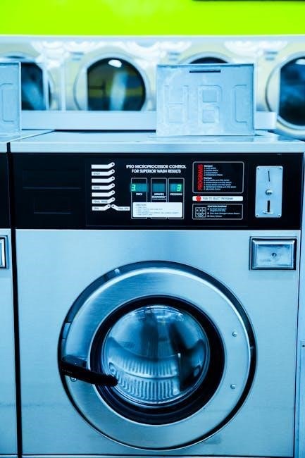
Control Panel Overview
The control panel of the GUD27ESSMWW laundry center features a cycle selection knob, enabling users to choose from a range of wash and dry cycles․ A prominent Start button initiates the selected cycle, while other buttons likely control functions like temperature settings, spin speed adjustments, and drying levels․ The panel’s design prioritizes intuitive operation, allowing for easy cycle customization․
Accessing Field Service Mode is achieved by a specific sequence: holding the Start button, rotating the cycle knob 180 degrees, and then releasing the Start button․ Once activated, all LEDs will blink, indicating entry into diagnostic mode․ This mode facilitates advanced troubleshooting and component testing․ Detailed explanations of LED blink codes and service functions are found within the complete service manual for technicians․
Troubleshooting Common Issues
Addressing typical malfunctions like a washer failing to start or a dryer not heating is crucial; error codes provide valuable diagnostic insights for swift resolution․
Washer Not Starting
When the GUD27ESSMWW washer fails to initiate a cycle, several potential causes should be investigated systematically․ First, verify the power supply to the unit, ensuring the outlet is functioning correctly and the circuit breaker hasn’t tripped․ Next, confirm the door is securely latched, as a safety interlock prevents operation if the door isn’t fully closed․
Inspect the start/pause button for proper functionality; a faulty button can interrupt the starting sequence․ Additionally, examine the water inlet valve for obstructions or failures, as insufficient water supply can hinder the wash cycle’s commencement․ Accessing Field Service Mode can reveal diagnostic error codes, providing clues about the underlying issue․ A thorough check of the wiring harness and control board is also recommended to identify any loose connections or component malfunctions that might be preventing the washer from starting․
Dryer Not Heating
If the GUD27ESSMWW dryer isn’t producing heat, a systematic diagnostic approach is crucial․ Begin by verifying the power supply and ensuring the lint filter is clean, as a clogged filter restricts airflow and can trigger a safety shutoff․ Next, inspect the heating element for continuity using a multimeter; a broken element will obviously not generate heat․
Check the thermal fuse and thermostat, as these components protect against overheating and will interrupt power to the heating element if they fail․ A malfunctioning gas valve (for gas dryers) or a faulty control board can also prevent the dryer from heating․ Utilizing Field Service Mode can display error codes that pinpoint the source of the problem․ Always disconnect power before accessing internal components and carefully examine wiring connections for any signs of damage or corrosion․
Error Codes and Their Meanings
The GE GUD27ESSMWW laundry center utilizes error codes to signal specific malfunctions, aiding in efficient troubleshooting․ While a comprehensive list requires the full service manual (PUB 31-9292-1), understanding the system is vital․ Accessing Field Service Mode allows technicians to view these codes directly via LED blink patterns․
Common issues often manifest as specific code sequences․ For example, codes related to water inlet valve failures, drain pump obstructions, or temperature sensor errors will be displayed․ Referencing the official service documentation is paramount for accurate interpretation․ Incorrectly diagnosing based on assumed meanings can lead to unnecessary component replacements․ Always document the error code observed before initiating any repair procedures, ensuring a focused and effective service call․
Service Mode Access & Functionality
Entering Field Service Mode on the GUD27ESSMWW requires holding the start button, turning the cycle knob 180 degrees, and then releasing the start button․
Entering Field Service Mode
Accessing Field Service Mode on the GE GUD27ESSMWW laundry center is a crucial step for advanced diagnostics and testing procedures․ To initiate this mode, a specific sequence must be followed precisely․ Begin by firmly pressing and holding the ‘Start’ button on the control panel․ While continuously holding the ‘Start’ button, rotate the cycle selector knob a full 180 degrees in either direction․
It’s important to maintain pressure on the ‘Start’ button throughout the entire rotation of the cycle knob․ Once the 180-degree rotation is complete, immediately release the ‘Start’ button․ Successful entry into Field Service Mode is indicated by all LEDs on the control panel beginning to blink simultaneously․
This blinking confirmation signifies that the unit is now operating in a diagnostic state, allowing technicians to perform a range of tests and access hidden functions․ Remember to consult the full service manual for detailed instructions on utilizing the features within Field Service Mode․
LED Blink Codes in Service Mode
Within Field Service Mode on the GE GUD27ESSMWW laundry center, the appliance communicates diagnostic information through a series of LED blink codes․ These codes are essential for pinpointing the source of malfunctions and guiding repair efforts․ The specific pattern of blinking LEDs – which lights are active, their sequence, and the duration of each blink – corresponds to a particular error or system status․
Technicians must refer to the comprehensive service manual to accurately interpret these blink codes․ The manual provides a detailed chart mapping each code combination to a specific component failure, sensor issue, or operational problem․
Understanding these codes eliminates guesswork and streamlines the troubleshooting process, leading to faster and more effective repairs․ Always document the observed blink code sequence before proceeding with any component replacement or adjustment․
Using Service Mode for Diagnostics
Once entered, Field Service Mode on the GUD27ESSMWW laundry center unlocks advanced diagnostic capabilities, allowing technicians to thoroughly assess the washer’s functionality․ This mode facilitates testing of individual components, monitoring sensor readings, and initiating specific operational cycles for diagnostic purposes․ It’s a powerful tool for isolating issues beyond what standard operation reveals․
Technicians can utilize Service Mode to manually control various aspects of the washer, such as the water inlet valve, drain pump, and agitator, to verify their proper operation․ Observing the system’s response to these manual commands provides valuable insights into potential failures․
Careful observation of LED blink codes, combined with component testing within Service Mode, ensures accurate diagnosis and efficient repair of the appliance․
Component Location and Replacement
Accessing internal components requires careful disassembly, while replacement of parts like the water inlet valve or heating element demands adherence to safety protocols and procedures․
Accessing Internal Components
Gaining access to the internal components of the GUD27ESSMWW laundry center necessitates a systematic approach to disassembly․ Begin by disconnecting the unit from the power source – a crucial safety precaution․ The top panel is typically secured with screws located at the rear of the appliance; removing these allows for lifting and tilting the panel forward․
Once the top panel is removed, you’ll have access to the control panel assembly and various internal components․ Further disassembly may involve removing side panels, often held in place by clips or screws․ Exercise caution when handling these panels to avoid damaging them․ The washer and dryer sections are largely self-contained, but interconnected by common components like the water supply lines and drain hose․
Before proceeding with any repairs, carefully document the location of wires and connectors to ensure proper reassembly․ Taking photographs during the disassembly process can be incredibly helpful․ Remember to consult the service manual for detailed diagrams and specific instructions related to component removal and replacement․
Replacing the Water Inlet Valve
To replace the water inlet valve on the GUD27ESSMWW, first disconnect the power and water supply․ Locate the valve, typically at the rear of the washer compartment, where the water hoses connect․ Disconnect the hoses, noting their positions for correct reattachment․ Carefully disconnect the electrical connector supplying power to the valve․
Remove any retaining clips or screws securing the valve to the appliance frame․ Gently pull the old valve out, observing the orientation of any seals or gaskets․ Before installing the new valve, inspect the inlet screens for debris and clean them if necessary․
Install the new valve, ensuring it’s properly seated and secured with the retaining clips or screws․ Reconnect the electrical connector and water hoses, verifying a tight seal․ Finally, restore power and water, and test the valve for leaks and proper operation through a wash cycle․
Replacing the Heating Element
Prior to replacing the heating element in the GUD27ESSMWW dryer, absolutely disconnect the power supply․ Access the heating element housing, usually located at the rear of the dryer cabinet, requiring panel removal․ Disconnect the wires connected to the heating element terminals, carefully noting their positions for reassembly․
Remove the mounting screws or clips securing the element to the support bracket․ Gently pull the old heating element out of its housing․ Before installing the new element, inspect the housing for any obstructions or debris․
Install the new heating element, ensuring it’s fully seated and secured with the mounting hardware․ Reconnect the wires to the correct terminals․ Reassemble the dryer panels, restore power, and test the new element by running a timed dry cycle, verifying proper heating․
Safety Precautions
Always disconnect power before servicing the GUD27ESSMWW laundry center to prevent electrical shock․ Handle components with care, following established safety guidelines diligently․
Electrical Safety Guidelines
Prior to any service procedure on the GUD27ESSMWW laundry center, absolutely disconnect the appliance from the main power supply․ This is paramount to prevent severe electrical shock or potential electrocution․ Verify the power is off using a reliable voltage tester, confirming no live current is present at the connection points․

Never work on electrical components with wet hands or while standing in a damp environment․ Ensure the work area is well-lit and free from obstructions․ When replacing wiring or electrical parts, always use components that meet or exceed the original manufacturer’s specifications․ Improperly installed or mismatched parts can create a fire hazard or damage the appliance․
Always discharge any capacitors before handling them, as they can store a dangerous electrical charge even after the power is disconnected․ If you are unfamiliar with electrical safety procedures, consult a qualified electrician before attempting any repairs․ Remember, safety is the top priority when working with electrical appliances;
Disconnecting Power Before Service
Before initiating any diagnostic or repair work on the GE GUD27ESSMWW laundry center, complete disconnection from the electrical supply is non-negotiable․ Locate the power cord and remove it from the wall outlet․ For hardwired installations, switch off the corresponding circuit breaker at the main electrical panel․ Double-check with a voltage tester to confirm absolutely no power is reaching the unit․
Simply switching off the appliance’s power button is insufficient; a complete physical disconnection is required․ This precaution safeguards against accidental energization during service, preventing electrical shock and potential damage to the appliance’s sensitive electronic components․ Always inform others in the vicinity that you are working on the appliance and that the power is disconnected․
Re-establish power only after all repairs are completed, and all components are correctly reassembled and secured․ Failure to follow these guidelines could result in serious injury or appliance malfunction․
Proper Handling of Components
When accessing and replacing internal components within the GE GUD27ESSMWW laundry center, exercise extreme care to prevent damage․ Utilize appropriate tools – avoid forcing parts, as this can lead to breakage or deformation․ Sensitive electronic modules, such as the control board, are susceptible to static discharge; employ a grounded wrist strap during handling․
Carefully label and organize removed parts, noting their orientation and connections for correct reassembly․ Store components in a clean, dry environment to avoid corrosion or contamination․ When dealing with the water inlet valve or heating element, inspect for any signs of wear or damage before installation․

Dispose of defective parts responsibly, following local regulations․ Improper handling can compromise the appliance’s functionality and void any applicable warranties․